域财网
域财网瑞萨RL78/F22 MCU基于e2studio开发环境创建触摸应用样例工程
目 录
| 01 | 概述 |
| 02 | 瑞萨RL78/F22 Target Board简介 |
| 03 | 基于e²studio创建触摸应用样例工程 –在e²studio中创建新工程 –在Smart Configurator中为新工程添加驱动程序 –使用QE for Capacitive Touch开发触摸应用 –添加应用代码实现LED闪烁 |
1
概述
本文包含以下主要内容:
瑞萨RL78/F22 Target Board简介
基于e²studio创建触摸样例工程
使用QE for Capacitive Touch开发触摸应用
触摸和LED闪烁演示
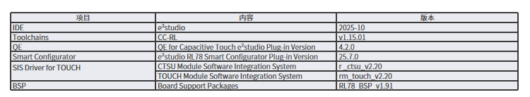
本文基于以下开发环境
软件运行环境
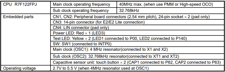
硬件运行环境
2
瑞萨RL78/F22 Target Board简介
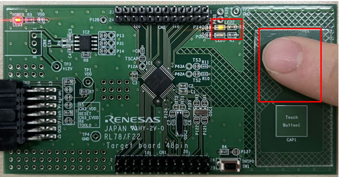
瑞萨RL78/F22 target board
(RTK7F125FPC01000BJ)
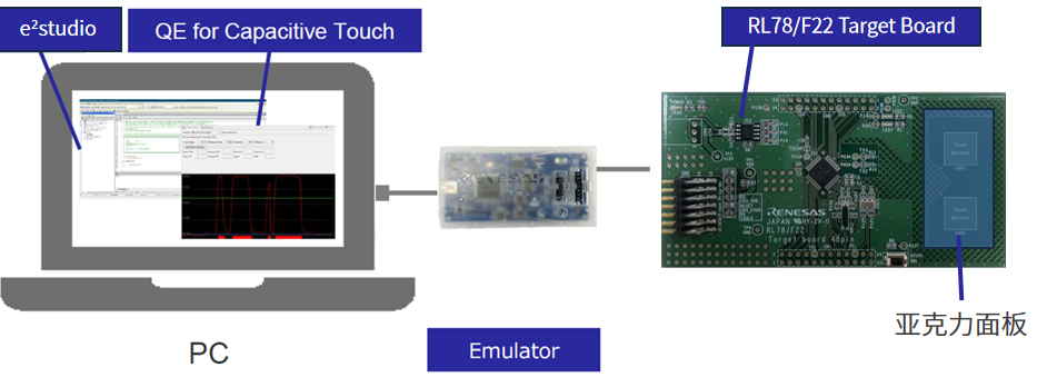
硬件运行环境搭建
硬件连接框图
3
基于e²studio创建触摸样例工程
在e²studio中创建RL78新工程
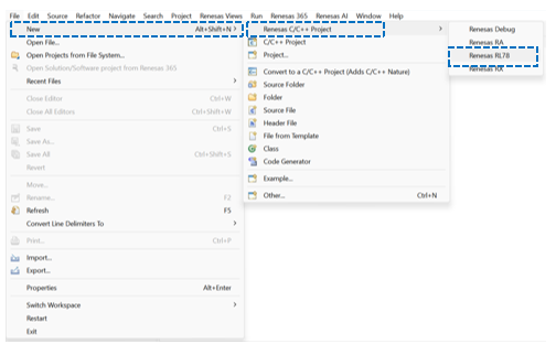
打开e²studio设定workspace后在菜单栏点击[File]新建RL78新工程。
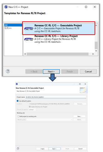
新建工程名称:
RL78F22_TB_TOUCH_SAMPLE
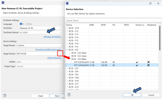
选择Toolchain
V1.15.01
选择目标器件
R7F122GG4xFB
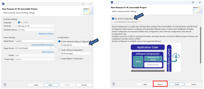
选择仿真器:
E2 Lite(RL78)。
选择Use Smart configurator
勾选。
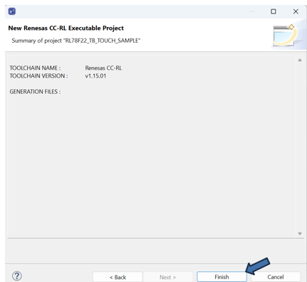
完成新工程创建
点击Finish。
在Smart Configurator中为新工程添加驱动程序
RL78新工程创建完成后,默认打开Smart Configurator的Overview选项卡。
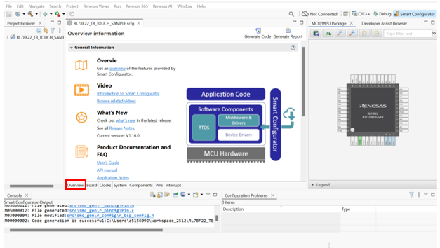
Smart Configurator设定
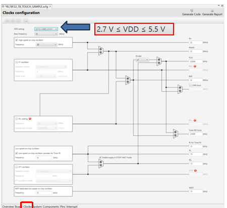
Clocks选项卡
设定VDD Setting
本例为2.7V ≤ VDD ≤ 5.5V。
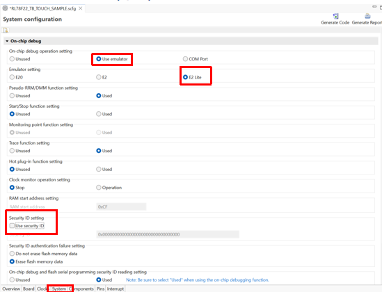
System选项卡
按照下图进行设定
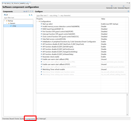
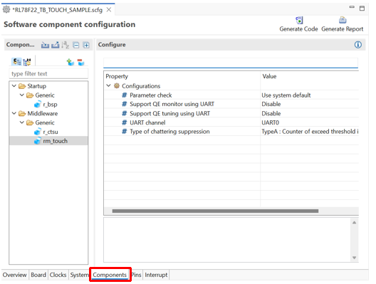
Components选项卡
r_bsp设定
保持默认。
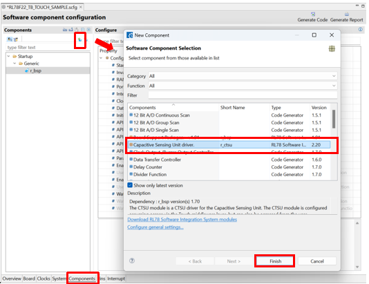
Components选项卡
点击

按钮。
在New Component对话框中选择Capacitive Sensing Unit driver.(r_ctsu)。
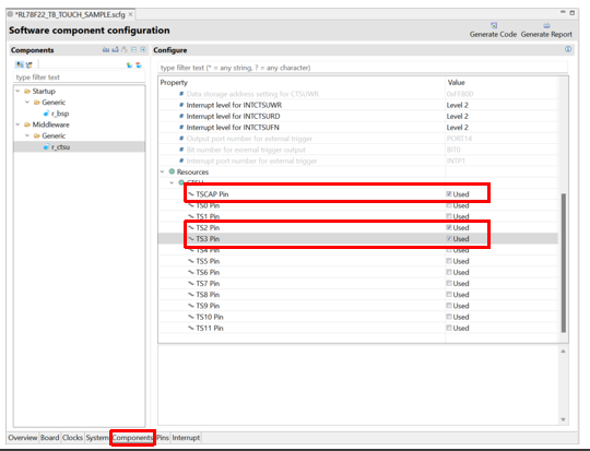
Components选项卡
r_ctsu设定
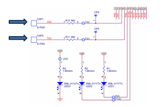
根据实际电路设定触摸通道:
勾选TSCAP;
勾选TS2;
勾选TS3;
按下图所示:
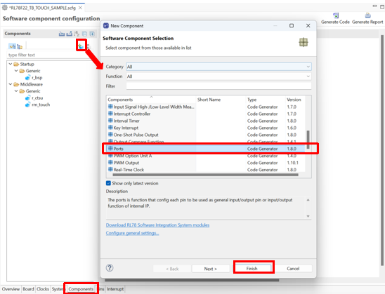
Components选项卡
点击
按钮。
在New Component对话框中选择Touch Middleware.(rm_touch)。

Components选项卡
rm_touch设定
按下图所示:
Components选项卡
点击
按钮。
在New Component对话框中选择Ports。
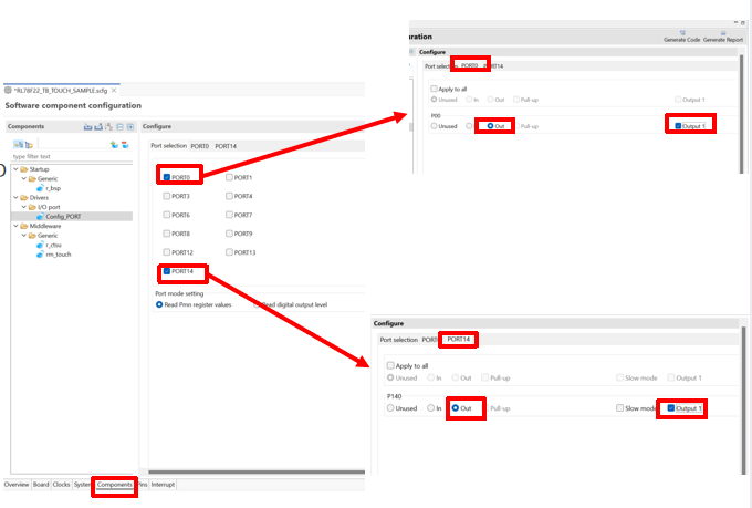
Components选项卡
Ports设定
用于驱动Test LED;
按下图所示:

Components选项卡
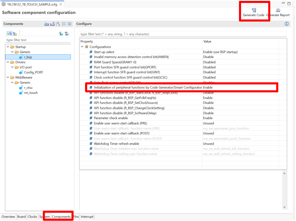
确认r_bsp。
Initialization of peripheral functions by Code Generator/Smart Configurator;
Enable;
点击
生成驱动程序。
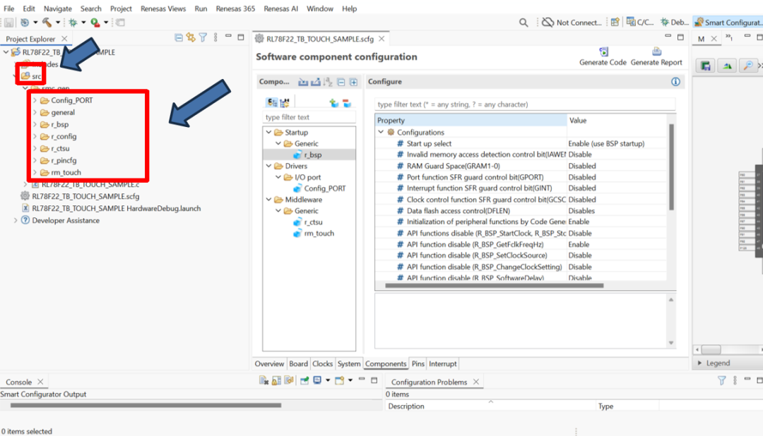
确认驱动程序的添加
点击

编译工程。
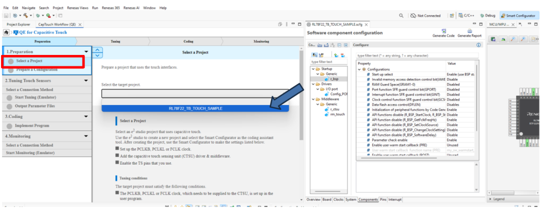
使用QE for Capacitive Touch开发触摸应用
在e²studio中打开QE For Capacitive touch

Preparation
工程设定
建立配置
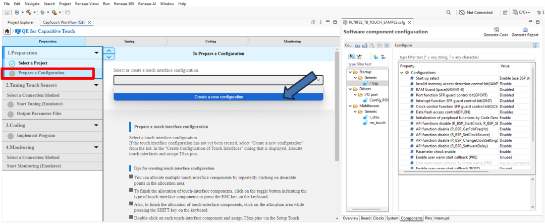
建立配置
在画布中添加Button
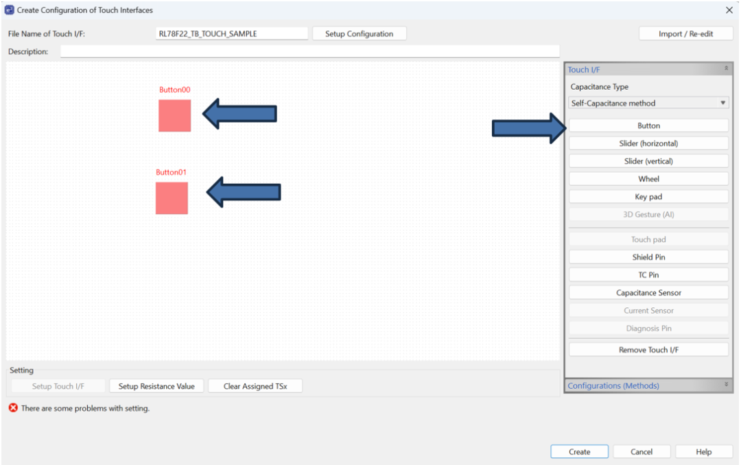
建立配置
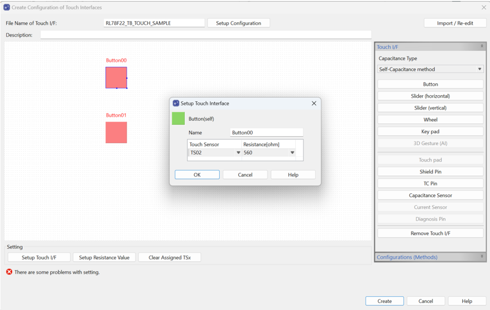
为Button设定触摸通道和阻尼电阻(Button00/TS02/560ohm,Button01/TS03/560ohm)。
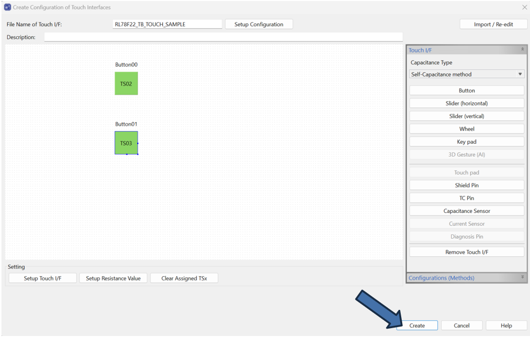
建立配置
点击Create完成设定。
Tuning
调优(Tuning)前的准备工作
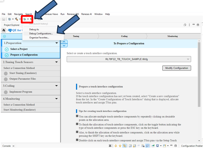
点击

旁边的

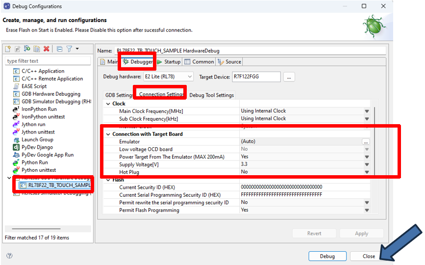
在下拉菜单中选择Debug Configuration。
双击对话框左侧的RL78F22_TB_TOUCH_SAMPLE_HardwareDebug后,在对话框右侧Debugger选项卡的Connection Settings标签页确认目标板供电方式为仿真器供电方式,点击Close关闭。
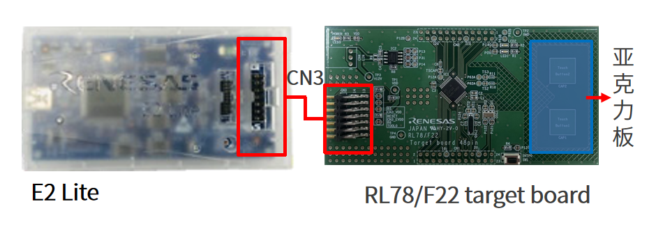
将E2 Lite连接PC以及RL78/F22 target board的CN3。
使用长45mmx宽25mmx厚2mm的亚克力板(用户自行准备)覆盖住电极区域。
注意:禁止手指直接触摸电极,否则会导致短路或者测量不正确。
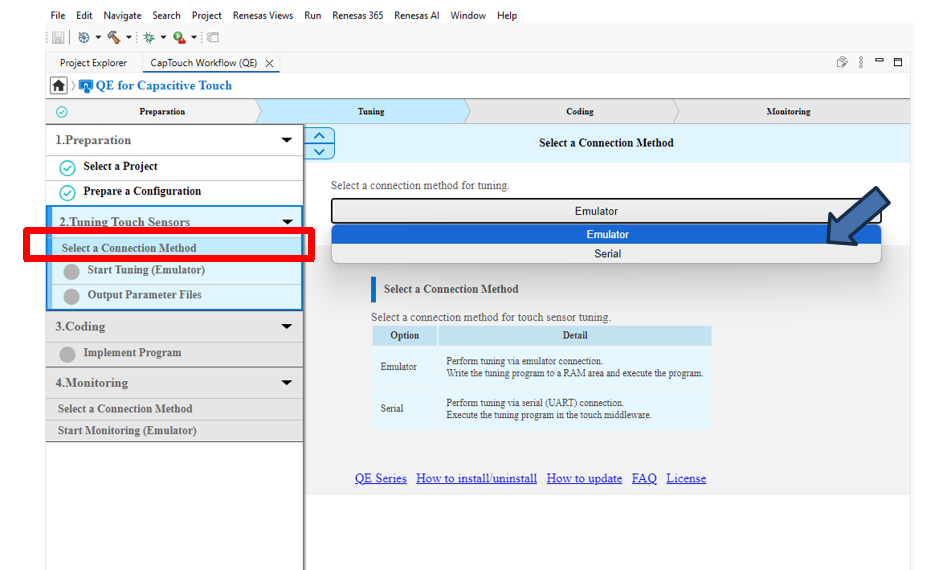
连接方法选择Emulator。
进行自动调优(Tuning)
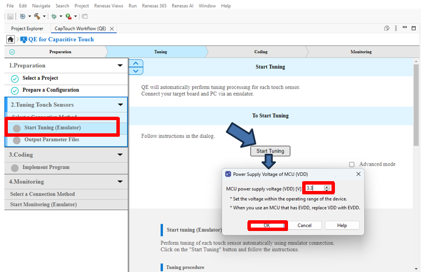
点击Start Tuning按钮,在弹出的对话框中,设定3.3V供电电压后,点击OK。
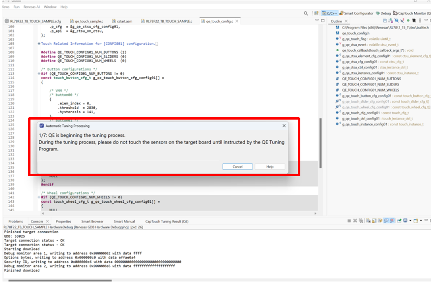
按步骤显示自动调优(Tuning)对话框,如寄生电容测量,偏置电流调整等无需用户操作的步骤。
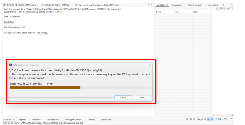
进入需要用户参与的灵敏度测量步骤
用户需要使用正常压力按压触摸按键并保持,然后按下PC键盘上的任意键,生成默认的阈值,完成调优(Tuning)。
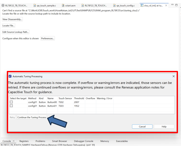
在弹出的对话框中,显示阈值/溢出信息/警告错误信息,用户点击Continue the Tuning Process按钮完成。
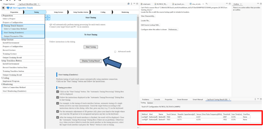
自动调优(Tuning)完成后,点击Display Tuning Result按钮,显示自动调优(Tuning)的结果,包括寄生电容值、驱动频率、阈值、扫描时间等。
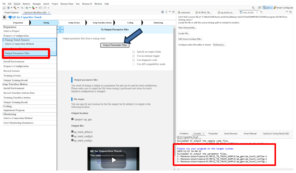
输出自动调优(Tuning)产生的参数文件
点击Output Parameter Files
Coding
输出Sample Code
点击Show Sample按钮,在弹出的对话框中,点击Output to a file,点击OK关闭。
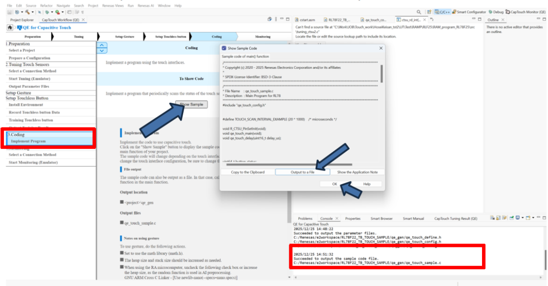
在工程目录下检查新生成的参数文件和Sample Code文件。
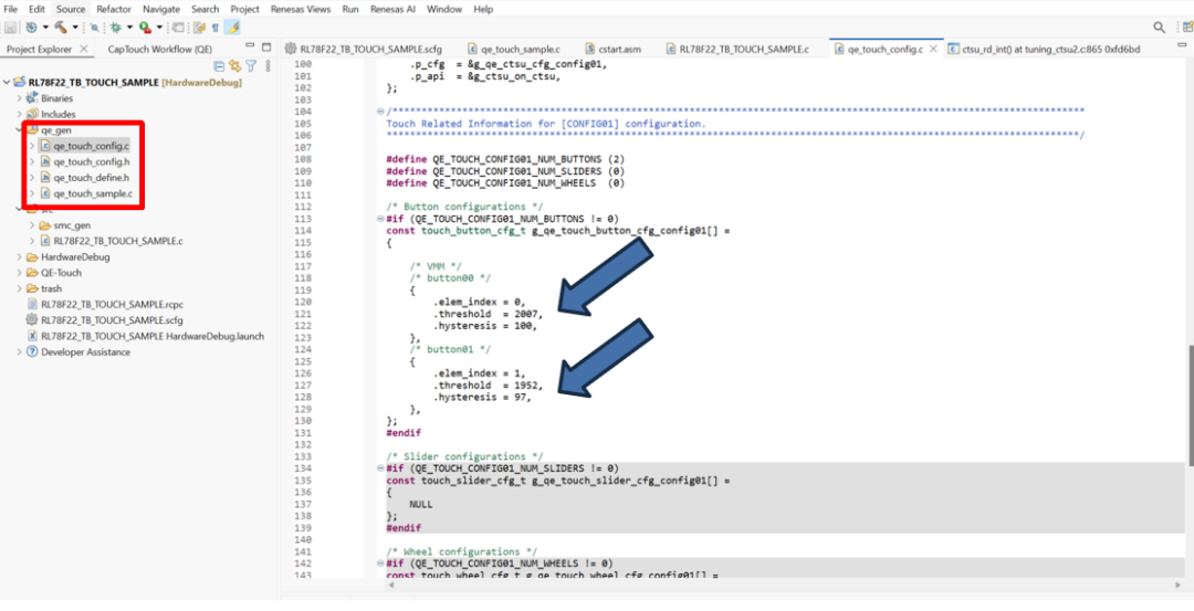
在qe_touch_config.c中检查的按键阈值(threshold)等参数。
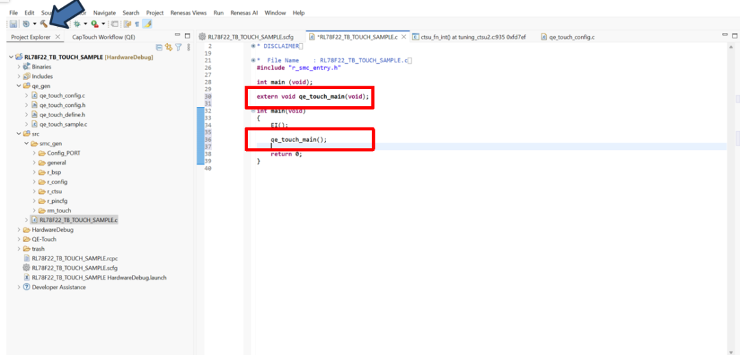
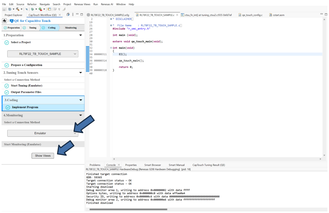
在main.c中添加qe_touch_main()的声明和调用
点击
编译工程,并运行程序。
Monitoring
确认连接方式为Emulator
点击Show Views
在Board Monitor中,点击Enable Monitoring ,并在各个监控窗口中设定需要监控的Touch I/F。
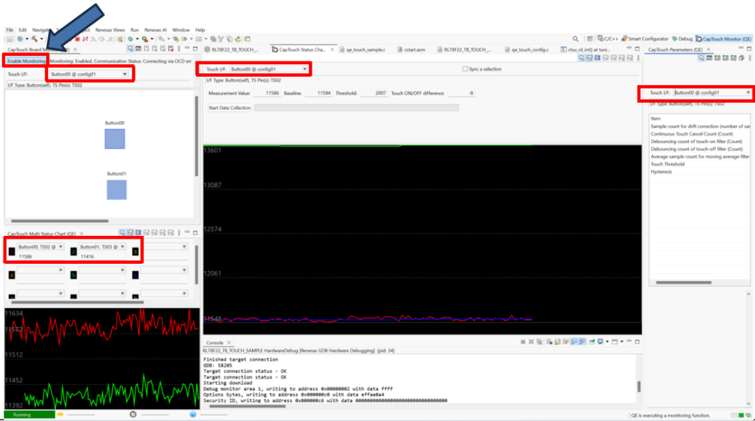
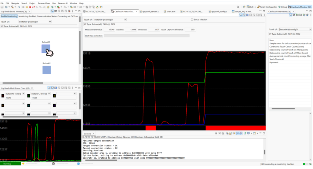
按下触摸按键,即可在各个图形化窗口中进行Monitoring以及触摸参数调整。
添加应用代码实现LED闪烁
应用代码添加
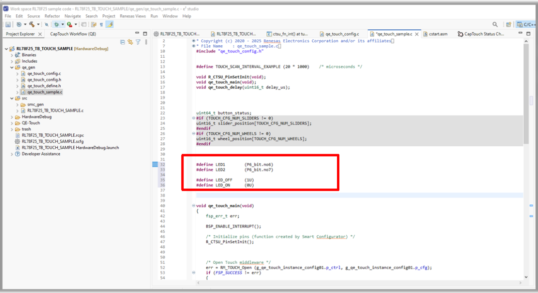
在qe_genqe_touch_sample.c中
LED1和LED2的宏定义
左右滑动查看完整内容
#defineLED1    (P6_bit.no6)
#defineLED2    (P6_bit.no7)


#defineLED_OFF   (1U)
#defineLED_ON   (0U)
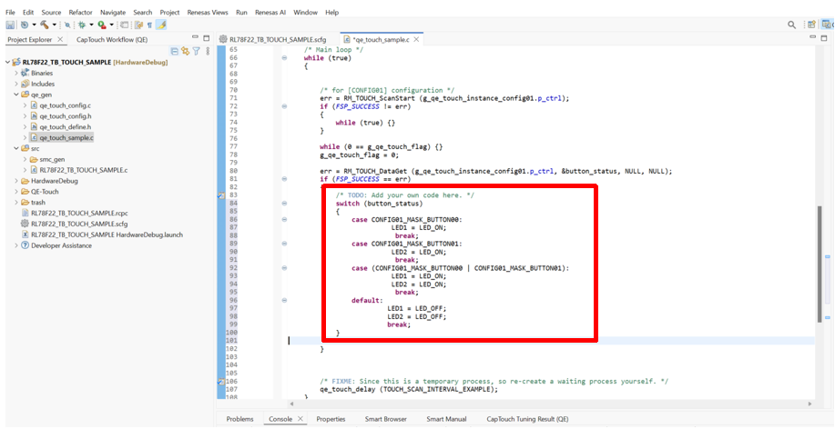
在qe_genqe_touch_sample.c中
按下触摸按键后点亮LED1和LED2。
左右滑动查看完整内容
/*TODO:Add your own code here. */
switch(button_status)
{
caseCONFIG01_MASK_BUTTON00:
LED1 = LED_ON;
break;
caseCONFIG01_MASK_BUTTON01:
LED2 = LED_ON;
break;
case(CONFIG01_MASK_BUTTON00 | CONFIG01_MASK_BUTTON01):
LED1 = LED_ON;
LED2 = LED_ON;
break;
 default:
 LED1 = LED_OFF;
 LED2 = LED_OFF;
 break;
 }
编译运行后,按下触摸按键Touch Button1点亮LED1。

编译运行后,按下触摸按键Touch Button2点亮LED2。